Optimizing Field of View and Resolution in Microscopy

Introduction

Maximizing the on-sample field of view in fluorescence microscopy is of increasing relevance across a wide range of applications, including high content screening of large fields of cells, imaging of the developing embryo, neuron mapping and tissue imaging.

Selecting the right camera to match with your chosen objective for maximizing field of view, while maintaining good imaging clarity, can be a daunting endeavour to many. In this technical note, we cover the primary considerations and provide a guide to matching camera sensor properties to the microscope’s magnifying conditions, without going into exhaustive detail.

Key Parameters and Trade-offs

When matching camera to magnification conditions, there are some fundamental considerations to balance:

  • Resolving Capability (Nyquist Over-sampling) – This concerns matching magnification and objective Numerical Aperture (NA) to pixel size, such that we are sufficiently over-sampling the optical diffraction limit. However, the smaller the pixel, or the greater the magnification we use to achieve this condition, the fewer photons we will collect per pixel, thus adversely influencing signal to noise ratio. To compensate for reduced signal to noise, we are often tempted to use higher illumination intensity (not good for live cell phototoxicity or dye photobleaching) and/or longer exposure times (not good for following dynamic events).
  • Sensor size – Ideally we want to adopt an optical approach that fills the entire available sensor area, thus maximizing field of view. For sensors that are larger than the Field Number of the microscope, we can use an additional magnifying coupler, readily available from Andor for use with the large field of view Sona 4.2B-11 back-illuminated sCMOS (see Appendix). Again though, a trade-off to be borne in mind is that greater magnification, while helping attain Nyquist clarity, results in fewer photons per pixel.

Key camera parameters to consider in this exercise are:

  • Pixel size (given in µm)
  • Dimension of the sensor diagonal (given in mm)

Key microscope parameters to consider in this exercise are:

  • Objective magnification (e.g. 40x, 60x, 100x)
  • Objective NA
  • Additional coupler magnification
  • Field Number of microscope (given in mm)

Example Optical Configurations using Andor sCMOS Cameras

Tables 1 and 2 show a series of example optical configurations that can be obtained using a selection of Andor sCMOS cameras. Table 1 focuses on the back-illuminated Sona 4.2B-11 (4.2 megapixel) and Sona 2.0B-11 (2.0 megapixel) cameras, each with 11 µm pixel size. Table 2 focuses on the microlens front-illuminated Zyla 4.2 PLUS and Zyla 5.5 cameras, each with 6.5 µm pixel size.

Key Input Parameters

  • Sensor format (horizontal pixels x vertical pixels)
  • Pixel size
  • Objective magnification and NA
  • Coupler magnification (if applicable)

Key Output Parameters

  • Field of View on sample (mm)
  • Oversampling (number of pixels oversampling the resolution limit)
  • Minimum port diagonal required

Assumptions

  • We have used the Rayleigh equation for calculating the resolution limit
  • We are assuming that ideal oversampling is 2.3 or greater, but that between 2 and 2.3 will also yield acceptable resolving capability.
  • While a wide range of objective lenses exist with various combinations of magnifications and NA, for the purpose of this exercise we have attempted to select some common objective lens parameters: 100x with 1.49 NA; 60x with 1.4 NA; 40x with 0.95 NA.

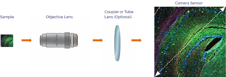
Schematic representation of how the sample area is captured and magnified onto the camera sensor

Figure 1: Schematic representation of how the sample area is captured and magnified onto the camera sensor. The challenge is to select an optical configuration and sensor selection that maximizes on-sample field of view while maintaining the ability to resolve fine structure.

Table 1: Example optical configurations that can be obtained using Sona 4.2B-11 (4.2 megapixel) and Sona 2.0B- 11 (2.0 megapixel) back-illuminated sCMOS cameras.

Key Conclusions from Table 1

  • Sona 4.2B-11, with the fully accessible 4.2 megapixel sensor, offers the largest on sample field of view while satisfying the NyQyist oversampling criteria for resolving clarity. For example, a 60x / 1.4NA objective combined with an additional 1.5x coupler magnification, means that a microscope port diameter of 21mm or greater can be used to image a large 0.35mm diagonal across the sample. Use of a 40x / 0.95 NA objective extends this to 0.53mm on-sample FOV diagonal, superb for developmental embryo imaging.
  • By carrying out the additional magnification onto the large 4.2 Megapixel sensor of Sona 4.2B-11, we can make use of relatively small microscope port sizes and Field Numbers, thus ensuring compatibility across a broad range of microscopes. See Appendix for details on the Andor Magnifying Coupler Unit, which can be ordered alongside the Sona 4.2B-11.
  • Sona 2.0B-11, with 2.0 megapixel sensor, offers a 22mm diagonal sensor and standard C-mount. This is an ideal match for modern microscopes that facilitate a 22mm c-mount port,1 maximizing the field of view available through this popular coupling standard.
  • The Sona 2.0B-11 model may be coupled with a 100x objective, without need for additional coupler magnification, yielding Nyquist oversampling. However, additional coupler magnification can of course be used to adapt the Sona 2.0B-11 for better use with 60x and 40x objectives.

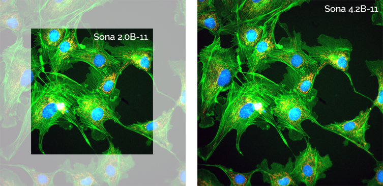
Figure 2: Field of View comparison between Sona 2.0B-11 and Sona 4.2B-11. Captured using a Nikon Ti2 with 60x objective and integrated 1.5x tube lens. The Sona 4.2B-11 has 114% more pixels and is ideally suited to maximizing the on-sample field of view. The Sona 2.0B offers a 22mm field of view and is ideally suited to 22mm C-mount ports.

Table 2: Example optical configurations that can be obtained using Zyla 5.5 / Neo 5.5 (5.5 megapixel) and Zyla 4.2 (4.2 megapixel) microlens front illuminated sCMOS cameras.

Key Conclusions from Table 2

  • Zyla and Neo cameras each offer smaller 6.5 µm pixels, thus are ideally suited to 60x and 40x objectives, achieving Nyquist oversampling of the diffraction limit without need for additional coupler magnification.
  • Zyla 5.5 and Neo 5.5, each housing a 5.5 Megapixel sensor, yield the largest available field of view with 60x objectives (0.36 mm) and 40x objectives (0.54 mm). These models, particularly with 40x objectives are superb for high content screening, tissue section and embryo imaging with high clarity.
  • Zyla 4.2 PLUS requires only a 19mm (or greater) C-mount microscope port, thus ensuring compatibility across a broad range of microscopes.
  • Zyla 5.5 and Neo 5.5 each offer a 22mm diagonal sensor and standard C-mount. This is an ideal match for modern microscopes that facilitate a 22mm c-mount port,1 maximizing the field of view available through this popular coupling standard.

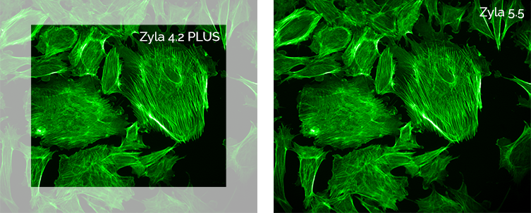
Figure 3: Field of View comparison between Zyla 4.2 PLUS and Zyla 5.5. The Zyla 5.5 has 32% more pixels and is ideally suited to maximizing the field of view from microscopes with a 22mm C-mount port.

Back-illuminated sCMOS FOV: Competitive Comparison

(a) Sona 4.2B-11 – Largest Field of View

The Sona 4.2B-11 model offers the largest field of view solution, compared to competitive back-illuminated sensors that also use the same GPixel GS400 BSI sensor type.

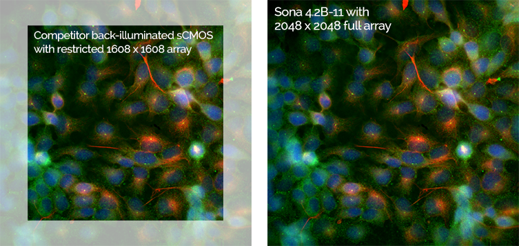
The Sona 4.2B-11 is native F-mount and can be compared against “Competitor A” below, a camera using the same sensor but cropped down to 1608 x 1608 pixel format. By cropping the sensor down, this camera can avoid sensor glow issues that affect the edges of this sensor. However, Sona 4.2B-11 uses a unique Anti-Glow Technology approach that enables the full native 2048 x 2048 of the array to be harnessed. Figure 2 shows the 62% larger field of view advantage offered by Sona 4.2B-11.

The Sona 4.2B-11 is native C-mount and can be compared against “Competitor B”, a camera using the same sensor but cropped down to 1200 x 1200 pixel format. Figure 5 shows the 38% larger field of view advantage offered by Sona 2.0B-11, while still fitting within a C-mount aperture. This is ideal for microscopes that offer a 22mm C-mount port. For mounting on microscopes with smaller ports, the user can readily choose one of the pre-defined Region Of Interest (ROI) sizes, or alternatively, the port can be used alongside a magnifying C-mount coupler.

Figure 4: “F-mount competitive solutions” - Field of View comparison between Sona 4.2B-11 and a competitor Fmount camera, utilizing the same GS400B back-illuminated sCMOS sensor but restricted to 1608 x 1608 max resolution. Captured using a Nikon Ti2 with 60x objective and integrated 1.5x tube lens. The Sona 4.2B-11 has 62% more active pixels and offers a compelling field of view solution.

(b) Sona 2.0B-11 – One camera, Multiple ports

The Sona 2.0B-11 is native C-mount and is adaptable to various microscope c-mount port diameters, up to 22mm. The 1400 x 1400 full array size of this model is suited to modern 22mm C-mount ports and maximizes the field of view available through this common mount type.

However, pre-configured, centrally positioned ROIs are available, directly relating to various smaller microscope port sizes:

Table 1: Pre-configured ROIs of the C-Mount Sona 2.0B-11 model, shown alongside the corresponding microscope Port Diameter / Field Number for which they are optimized.

Alternatively, smaller ports can be used with the full 1400 x 1400 array size by utilizing the Andor Magnifying Coupler Unit (see appendix). This is a coupler that can readily connect to the port, expanding the image available from the microscope onto the larger sensor area. A 2x coupler also has the benefit of achieving Nyquist resolution utilizing a 60x objective, which in turn further optimizes the on-sample field of view.

Appendix

Andor provide an optional Magnifying Coupler Unit (MCU) accessory which can be used alongside the Sona 4.2B-11 in order to utilize the full field of view of this large sensor with several common types of modern research fluorescence microscopes. It can be used to adapt both Sona 4.2B-11 or Sona 2.0B-11 for use with 60x and 40x objectives, thus increasing the on-sample field of view while also maintain Nyquist resolving clarity. Since the image is being 2x magnified onto a 32mm diameter sensor area, then the MCU can be attached to any port that offers an image output of 16mm or greater. This describes the vast majority of available ports.

For further details, please refer to the specification sheet for the Andor Magnifying Coupler Unit.

Figure 6: Andor’s Magnifying Coupler Unit

References

  1. Nikon Eclipse Ti2 dimensions: https://www.nikon.com/products/microscope-solutions/lineup/inverted/ti2/spec.htm

Date: N/A

Author: Andor

Category: Technical Article

Download as pdf

Share

Related assets